Fig. 1

The design for gaps (A) must be as small as possible. The smaller the gap the larger the labyrinth or sealing effect.
Please refer to the information in the respective data sheets for the different ring designs under “Axial and/or radial play” if radial play and/or tilting motions are detected!
Fig. 2

The use of attachable installation tools for the housings and removable installation tools for shafts are recommended if the specified installation chamfers are not possible at the housing or shaft for space reasons.
Do not only press when assembling the parts equipped with rings but overcome the slip resistance by radial motion and axial tapping.
Fig. 3

- Single and double wound laminar rings are spiraled into the grooves by axially spreading the rings.
- Care must be taken to ensure the rings are not over stretched, as they will be permanently deformed.
Fig. 4

Do not spiral the ring ends into each other or jam them when the single wound laminar rings are spiraled into the grooves.
Do not spiral the ring ends or the windings into each other or jam them when the double wound laminar rings are spiraled into the grooves.
Fig. 5

As shown, inside and outside clamping laminar rings can be installed through spiraling by hand. Spread ring slightly axially
- Insert one ring end into the groove.
- Slide remaining part of the ring spirally.
Fig. 6

The shaft retaining rings can also be installed with a support tool (see figure) to replace spiraling by hand.
- Attach installation cone and retaining ring.
- Slide the retaining ring with the help of the push sleeve over the installation cone.
- Check the secure installation of the ring in the groove.
Fig. 7

The bore retaining rings can also be installed with a support tool (see figure) to replace spiraling by hand.
- Attach installation tapered sleeve and retaining ring.
- Slide the retaining ring with the help of the push sleeve over the installation tapered sleeve.
- Check the secure installation of the ring in the groove.
Fig. 8

Disassembly of the retaining rings with the help of a flat-bladed screwdriver. The screwdriver is inserted into the disassembly notch and rotated slightly so that one ring end of the retaining ring slides out of the groove. The ring will be removed spirally from the groove.
Greasing
General information for greasing:
Greased laminar rings provide a better seal arrangement than dry running rings, greased laminar rings are required when the application is subject to splash water, dirt and scale. In order to allow sufficient transfer of grease throughout arrangement and prevent over pressure during application, it is recommended that grease application bores and grease relief bores are provided. Where possible the ring carrier should be supplied by 4 off 3 to 5 mm diameter bores equally distributed around the circumference and also into the groove base, this will allow easy application and exchange of grease during re-lubrication.
Greasing options:
Listed below are three different and proven greasing options with greasing bores or grease relief bores, which can be arranged depending on the available space. Leakes from the outside are not possible because the bores are filled with grease.
Lubrication recommendation:
We cannot make any recommendations for the selection of the lubricant or provide information about the greasing frequency. The type and quantity of an appropriate lubricant must be determined and specified by the customer depending on the operating conditions such as speed, operating temperatures, contamination level and ambient conditions. Bearing and lubricant manufacturers may be able to provide information.
Note:
“FK5-HFL” ring types are the exception with respect to greasing. They must be installed dry and without any additional lubricants. The surrounding components, which come in contact with the laminar rings must also not be greased. The lubricants carbonize due to the high operating temperatures and the laminar rings will fail.
Application examples:
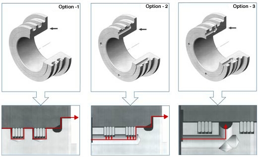
Option -1:
Grease relief bores, arranged vertically to the groove base, four for each grove circumferentially distributed at 90°. The bore diameter depends on the groove width. The grease pressed by the bearings can flow in next to the rings or can flow out upwards under the rings.
Option -2:
Grease relief bores, arranged horizontally to the groove base, four for each grove circumferentially distributed at 90°. The bore diameter should be between 3 and 5 mm. The grease pressed by the bearings can flow out upwards under the rings (groove base diameter) and next to the rings.
Option -3:
This greasing option is a combination of the above mentioned option 1 and 2. A so-called “grease chamber” is placed between the two sealing ring sets, this will act as a grease reservoir in the groove and therefore optimize the sealing effect.